Jacob Butler's Joinery Workshop: Woodwork Tips
2 How To Make Perfect Trestles, or a Lathe Stand
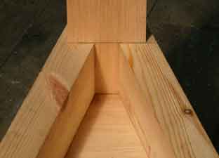
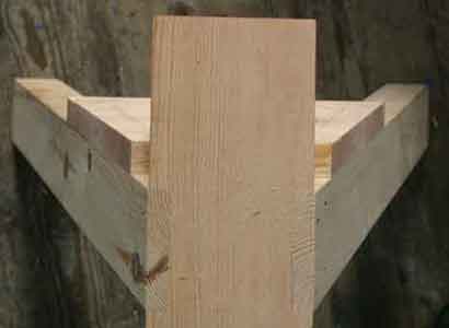
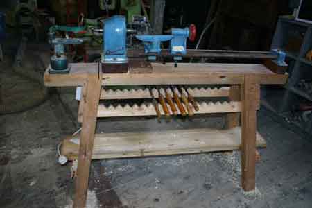
These traditional trestles are not as simple as they look. The splayed legs are rhomboid in section, which makes them appear square in plan. In many Carpentry and Joinery courses this is one of the basic exercises introducing roof geometry. It also produces beautiful trestles like these saw horses and gives you the ability to make other complicated structures like the lathe stand below.
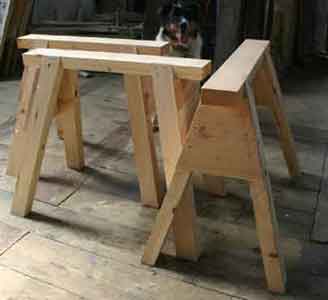
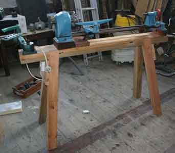
I would highly recommend this design for a lathe as it is very solid and stable. It also gives plenty of foot room. This example is made from old joists. The bottom shelf and tool rack are extras to the basic design.
This is a case of throwing in at the deep end! Step by step would be very prolonged. If you have any queries you could post them on the UK Workshop forum
The drawing and text below are taken from "Joinery & Carpentry " ed. Richard Greenhalgh, New Era Publications. This is an excellent 6 volume set which is widely available 2nd hand, usually as single volumes.
You have to start with your design drawing, which for this trestle is pretty simple - you just need your basic dimensions on a sketch.
Then there are 3 alternative things you can do next:
1 Put in your dimensions on the sketch and then work out dimensions and angles by trigonometry
2 Draw it up to small scale from your dimensions, and then take off scale measurements and angles direct, with or without trigonometry as well.
3 Draw it out full size to your dimensions (whole or half sheet of ply?) and use as a rod direct i.e. lay on your components and take off marks, lay on your sliding bevel for angles.
Option 3 is easiest (once you have got the hang of it!) and most accurate and the drawing does all the calculations for you. Here goes, copied direct from the book:
GEOMETRY OF THE SPLAY-LEGGED TRESTLE
The ordinary saw stool or trestle affords one of the best examples of the application of geometry to joinery work, since it involves nearly all the geometrical principles connected with the determination of bevels, sections, projections and true shapes of plane surfaces.
There are two distinct methods of dealing with the problem ; one, the more simple, making the right-angle section of the leg rhomboidal and its horizontal section rectangular ; and, two, using rectangular timbers which result in a rhomboidal horizontal section.
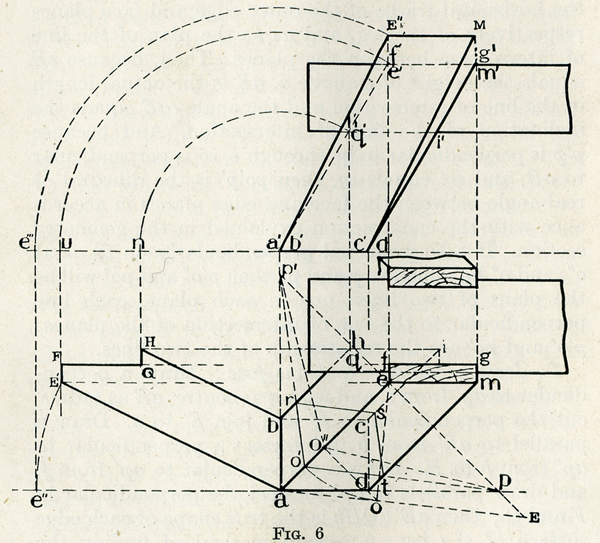
To determine the projections, developments, and bevels for an oblique trestle leg having a rectangular horizontal section.
Let ae and a'e' be the given projections of one long arris of one leg.
Draw eE at right angles to ae and equal to d'e' (the height of e' above a').
Join E to a and draw ap parallel to the ground line, p being in eE.
Draw a perpendicular to ap from a to meet eE produced in p'.
Draw eo perpendicular to aE, and with e as centre, turn o to o' ; and join o' to p and to p'.
Make o't and o'r equal to the required width and thickness respectively of the leg, and complete the parallelogram o'rst ; then a right-angle section through the required leg is equal to o'rst, and the angle between the faces and edges of the material is determined at p'o'p.
(NB "required width and thickness" is as measured across the faces, not perpendicular between the faces)
Through the points r, s and t, draw parallels to ae to meet ap' in b, a parallel to ap in c and ap in d; then abcd is the required rectangular horizontal section of the leg.
Draw a parallel to ap from e to meet dt produced in m ; then aemd is the plan of the outer face of the leg.
Project m to m' and d to d', and join m' to d' ; then a'e'm'd' is the elevation of the leg.
Let q' be the point in which a'e' meets the underside of the trestle top, and project q' to h in br produced.
Make ef along ee' equal to the required width of the upper horizontal surface of the leg, allowing for any desired recess in the edge of the trestle top, and complete the rectangle efgm.
Produce gf to meet q'h produced in q. Draw hi parallel to em, i being in cs produced ; the plan of the leg is now completed.
To explain the construction :
Regard ap' and ap as the horizontal traces of the outer edge and face planes respectively of the leg, and ae as the plan of the line of intersection between the planes.
Then, because eE equals the height of e above a, aE is the actual length of the line of intersection and the angle eaE equals the inclination of the line of intersection.
And because p'p is perpendicular to ae through e, eo is perpendicular to aE, and eo' equals eo, then po'p is the dihedral or real angle between the face and edge planes in accordance with the construction explained in the geometry section.
If o be projected perpendicularly on to ae at o" , and o" be joined to p and p' , then p'o" and po" will be the plans of two lines, one in each plane, each line perpendicular to the line of intersection of the planes ; p'o' and po' are the rabatments of the two lines.
To develop one edge and one face :
Draw a perpendicular to ap' from e, and with a as centre, aE as radius, cut the perpendicular in E' and join E' to a.
Draw a parallel to aE' from b to intersect a perpendicular to ap' from h in H.
Draw a perpendicular to ap' from f , and draw parallels to ap' to meet the perpendicular in F and Q ; then aE'FQHb is the true shape of each edge surface of the leg.
A second method of finding the edge development is shown, and is as follows :
Turn q' and e' about a' to meet the ground line in n and u, and project u and n into the perpendiculars to ap from h, q, and e to give H, Q, F, and E'.
To develop the outer face :
Turn E' to e" in pa produced, and project e" to e'" .
With a' as centre, turn e'" to E" in ee' produced, Join E" to a' and complete the rhomboid a'E"Mc' , the true shape of the required face.
And that's all there is to it. Easy peasy!
top of page